Modes Overview
Common Info
Note
To start creating objects, select the object in the inspector, select the desired spawn position, and press the E key to create the object (you can change the create hotkey to whatever you want).
Each edit mode has its own special features, which are described below.
Single Mode
The single mode is used for the positioning of single objects.
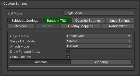
Object Mode
Create new
Create a new object by using different tools.
Select
Select an existing object in the scene and modify it using the various single edit tools described below.
Edit Mode
Simple
Spawn objects without any additional adjustments.
Custom handles
Create an object by modifying it with position, rotation and scale handles.
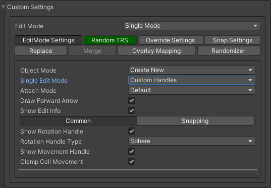
- Rotation handle type:
Sphere : edit object rotation with sphere handle.
Arc : edit object rotation with arc handle.

Cursor point rotation
Rotates the object in the direction of the cursor.

Custom point rotation
Rotates the object towards the target object.

Note
By default, you can change the scale of the object using the left-ctrl key and the mouse wheel keys.
Physics Placing
Place objects using physics.
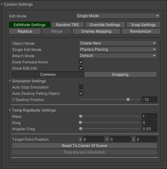
- Simulation settings:
Auto stop simulation : physics simulation will automatically stop after the objects are frozen in position.
- Auto destroy falling object :
Y destroy position : position below which physical objects are automatically destroyed.
- Temp rigidbody settings:
Mass : mass of temporarily created physical object.
Drag : drag value of temporarily created physical object.
Angular drag : angular drag value of temporarily created physical object.

Physics placing example.
Note
Rigidbody and collider components are automatically added temporarily if missing.
Attach Mode
Default
Default object placing.
Brush
Create an object on any collider or mesh surface of another object.
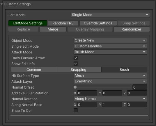

- Hit surface type:
Mesh : attach object to mesh.
Collider : attach object to collider.
- Normal rotation:
- Disableddefault object rotation.
Look normal : look normal method for the attached object.
Revert normal rotation : inverse normal direction of the surface hit.
- Along normalalong the normal method for the attached object.
Along normal base : normal base value (default Vector3(0,1,0)).
- Snap to cellsnap tile to cell grid (useful for attaching cube tiles).
Add surface pivot offset : adds a pivot offset of the object relative to the surface.

Snap cube to cell example.
Common Settings
Draw forward arrow : show forward rotation of target object.
Show edit info : show rotation and local of position of target object.
Snapping Settings
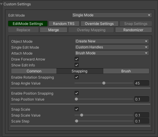
- Enable rotation snapping:
Snap angle value : value of rotation snapping.
- Enable position snapping:
Snap position value : value of position snapping.
- Enable scale snapping:
Snap scale value : value of scale snapping.
Scale step : value of the incrementing scale by key.
Brush Mode
Brush mode is used to position multiple objects on any surface.
How To Use
Press E key to spawn objects under the brush.
Attach Settings
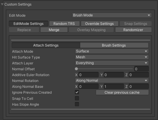
- Attach mode:
Default : default object placement.
Brush : create an object on any collider surface or meshes another object.
- Hit surface type:
Mesh : attach object to mesh.
Collider : attach object to collider.
- Normal rotation:
Disabled : default object rotation.
- Look normallook normal method for the attached object.
Revert normal rotation : inverse normal direction of the surface hit.
- Along normalalong normal method for the attached object.
Along normal base : normal base value (default Vector3(0,1,0)).
- Has slope angle
Slope angle value : angle to the surface at which objects can be created.
Brush Settings

- Randomize object countrandom count value of objects of the brush.
Min object count : minimum number of objects created at a time.
Max object count : maximum number of objects created at a time.
- Rotation along brusheach object is rotated along the brush creation line..
Additional rotation along brush : additional rotation offset for objects along line.

Brush example 1.

Brush example 2.

Brush example 3 (slope angle 30 degrees enabled).
Line Mode
Line mode is designed for placing objects along a line.
How To Use
Press the E key to start the line, when the line is set, press the E key again to spawn a line of the objects.
Line Type
Free
Places objects on a grid in the direction of the cursor.
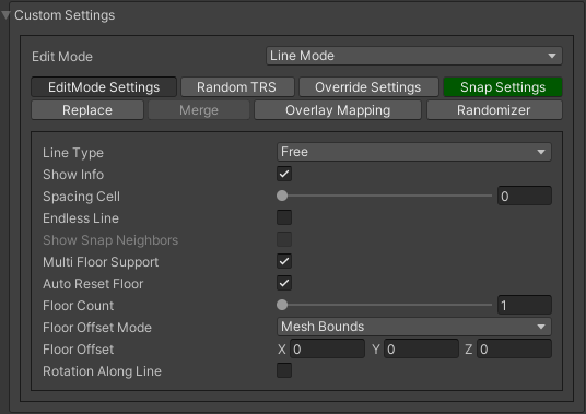

Free line example (endless line enabled).
Fixed
Create straight lines on a grid.
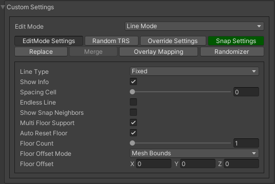
Free/Fixed line settings
- Multifloor:enable multi-floor feature
Auto reset floor : auto reset of floor count to 1 after deselecting.
Floor count : number of object floors.
- Floor offset mode:
Custom : user floor offset.
Mesh bounds : Y-axis size of mesh renderer floor offset.
Collider bounds : Y-axis size of collider floor offset.
Floor offset : additional floor offset.

Fixed line example (randomizer enabled).
Free/Fixed edge settings
Snap edge movement type should be enabled in the Overlay mapping tab.

- Add edge side offsetadds an offset to the side of the line.
Edge relative point : point relative to which the offset will be applied to the side.
Edge side offset : offset value to the side.

- Fixed line example:
Randomizer with pattern (01) enabled.
Snap edge enabled.
Edge side offset (0.5).
Note
Snap same floor feature for auto-snap available (Snap Settings tab).
Curved
Place objects along a curved line.

Common settings
- Curve line type:
Bezier
Simple line
Circle
- Snap type:
Disabled
Lock Y : Y position is fixed.
Auto Snap : the object of the curve is automatically attached to the surface.
- Object normal type:
Up
Curve direction
Surface normal
Custom : user normal.
Tabs
- Common
Loop line : should the line be looped.
Additive euler rotation : additional rotation for each object.
Flexible spacing : position of objects on the curve according to their size.
Spacing length : user spacing.
Clamp tangents : tangents move together relative to the central node.
- Custom
- Auto snap:
Attach to mesh : should the object be attached to the mesh.
Snap layer mask : layer for attaching objects.
Raycast direction : direction of the raycast.
Raycast distance : raycast from offset point to raycast direction distance.
Offset raycast distance : offset from zero Y surface.
- Visual
Curve color : color of the curve.
- Handles typehandle type for tangents.
Sphere
Position handle
Draw nodes : display handles of the nodes.
Draw buttons : display add/remove buttons of the curve segments.
Draw tangents : display tangents of the nodes.
Bezier segment line count : number of Bezier segments between nodes (the more segments, the more accurate the curve).

- Additional curve settings (:ref:`randomizer <randomizer>` window):
- Flexible spacing [enabled]:
- Ignore sizeobject size in the line is ignored.
Edge : object takes the rotation of the previous object, also the line is finished by this object.

- Simple line example:
Random pattern enabled.
Flexible spacing enabled (additional ignore size & edge enabled at the pillar in the randomizer window).

- Bezier line example:
Auto-snap enabled.
Random rotation enabled.

Circle line example (object random enabled).
Note
For simple line segment can be added by Ctrl and left-mouse click hotkeys.
Area Mode
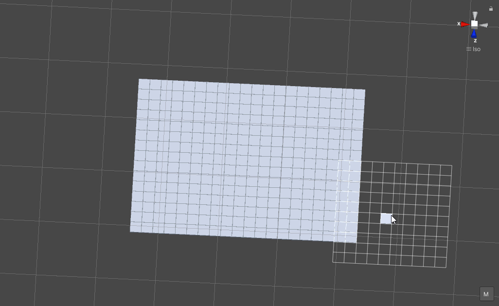
Area mode is designed for positioning objects by area.
How To Use
Press E key to start the area,

Once the area is set, press E key again to spawn the objects.
Settings

- Area mode type:
Default : placing the object set on the area.
Scale : scaling of a single object on an area.
- Multifloorenable multi floor feature
Auto reset floor : auto reset floor count to 1 after unselect.
Floor count : count of object floors.
- Floor offset mode:
Custom : user floor offset.
Mesh bounds : Y axis size mesh renderer floor offset.
Collider bounds : Y axis size collider floor offset.
Floor offset : additional floor offset.
Note
Snap same floor feature for auto-snap available (Snap Settings tab).
Destroy Mode
Destroy mode is designed for conveniently destroying objects in the scene.
How To Use
Press E key to start the destroy area, after the area is set, press the E key again to destroy the selected area.

Delete Mode
MapTile grid delete
- Delete floor method:
Disabled
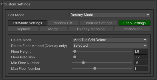
- Selectedselected floors are deleted.
Floor height : floor height in unity units.
Floor precision : offset on the edges between floors.
Min floor number : min floor number for delete.
Max floor number : max floor number for delete.

- Last countselected top floors are deleted.
Floor count : number of floors to remove.
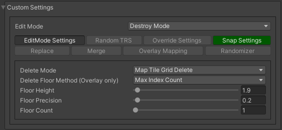
- Max index countonly floors with a maximum index will be deleted.
Floor count : number of floors to remove.

Last count remove example.

Selected 0 - 2 floors remove example.
Note
The floor delete method only works on GameObjects with MapTile component.
Enable auto-snap to snap the cursor to any surface.
Raycast deletion
Common settings
- Object type:
- Draw debugshow the bounds of the deletion process.
Debug color : debug colour.
Unique settings
- Box raycast
Y box offset : offset from surface.
Max box raycast distance : raycast distance from offset point.
- Brush raycast
Brush radius : radius of the delete brush.
- Attach to surface:
Attach layer : layer to which the brush is attached.
Y brush raycast normal offset : offset from brush hit surface.
Max brush raycast distance : raycast distance from offset point.
Note
How to use:
Press E key to destroy objects under the brush.

Box raycast remove example.

Brush raycast remove example.
Note
The raycast method only works on any GameObject with collider.
Screen selection
How To Use
Press the E key to start the selection box, after selecting the objects, press the Spacebar key to destroy them.

Screen selection remove example.
Settings
- Selection object method:
Multiple : all objects under the selection box are selected.
Single : only 1 object under the cursor is selected.
Auto destroy on select : object is automatically be deleted after selection.
Selection color : colour of the selection box.
Tileset Mode
Tileset area is used to create areas of linked tiles.
How To Use
Press E key to start the tileset area, after the area is set, press the E key again to spawn tileset area.
How To Create Tileset
Toggle Create new tileset settings.
Enter Tileset name.
Press Create button.

Drag and drop the desired prefabs into the box (the default prefab should drop first).


Press Open tile edit mode prefab to configure the tile set.
Select the cells where the connection of the tiles will be.
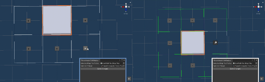
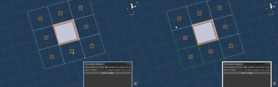


Tile connection setup example examples.

Create tileset area example.
Note
At the moment, the tilesets only work for flat tiles.
Settings
Translate Mode
Translate mode is used to move the set of objects.
How To Use
Press E key to start the selection area.
Move the scene handle to the desired position.
Press the E key again to translate selected objects.
Settings

Scene settings
- Movement type:
World cursor : objects move along the world cursor.
Scene handle : objects move along the scene handle.
- Translate mode:
Full translate : objects can only be moved only if all selected objects can be moved.
Partial translate : will be moved those objects that do not intersect other objects.
Can replace : intersected objects can be replaced when the selected objects are moved.
- Selection method:
Map : selecting objects on the grid.
Screen selection : selecting objects under the selection box.
Translate settings
- Show intersected objectsintersected objects will be highlighted.
Intersected objects color : the colour of the intersected objects highlighting.
Other settings
- Delayed heavy calculationcalculation of intersections will be delayed with a large number of objects.
Heavy calculation object count : count of objects to start a delay.
Calculation delay duration : duration of the delay after a position change.
Snap settings
- Snap to grid
- Snap grid enabledsnap to the grid.
Cell offset : value of offset in grid cells.
Custom Y Snap : custom snapping value for Y axis.
- Snap grid disabled:
- Translate snap typecustom snapping.
Snap translate : translation offset will be snapped.
Snap position : position of translated objects will be snapped.
Snap value
Note
Moving a large number of objects can take a very long time.
To quickly move a large number of objects, turn on Can replace mode and turn off Show intersected objects.
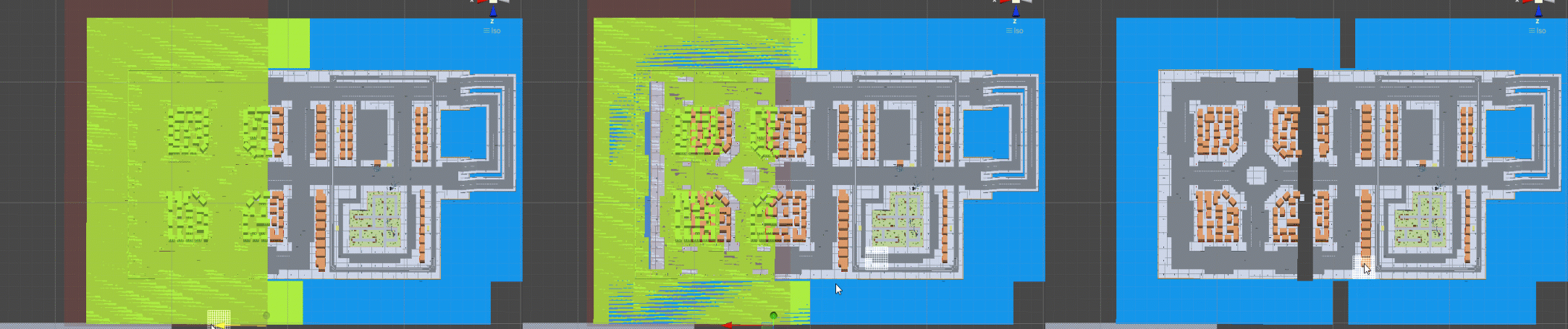
Translate mode example 1.

Translate mode example 2 (Red object is a source, blue object is the intersected object).
Create Template Mode
Template mode is designed to create template prefabs from existing prefabs.
How To Use
Press E key to start the selection area, after the desired objects are selected, configure the template parameters and click the Create button.

After the desired objects are selected, configure the template parameters.
Click the Create button.
Settings

- Selection method:
Map: selecting objects on the grid.
- Screen selection: selecting objects under the selection box.
Target layer : layer of objects to be selected.
- Selection object method:
Multiple : all objects under selection box will be selected.
Single : only 1 object under the cursor will be selected.
Selection color : color of the selection box.
- Template object type:
- Child prefab type:
Linked prefab : child objects of the template are linked prefabs.
Prefab clone: child objects of the template are prefab clones.
- Category type:
Template: template prefab is added to the template category.
- Custom: template prefab is added to the custom category.
Category: name of the custom category.
- Delete child components: delete all unity-components of the object.
Delete only MapTile: or only MapTile component
- Draw bounds: draw bounds of the template.
Y bounds size: Y bounds size of the template.
Bounds color: colour of the bounds.

Template mode example.